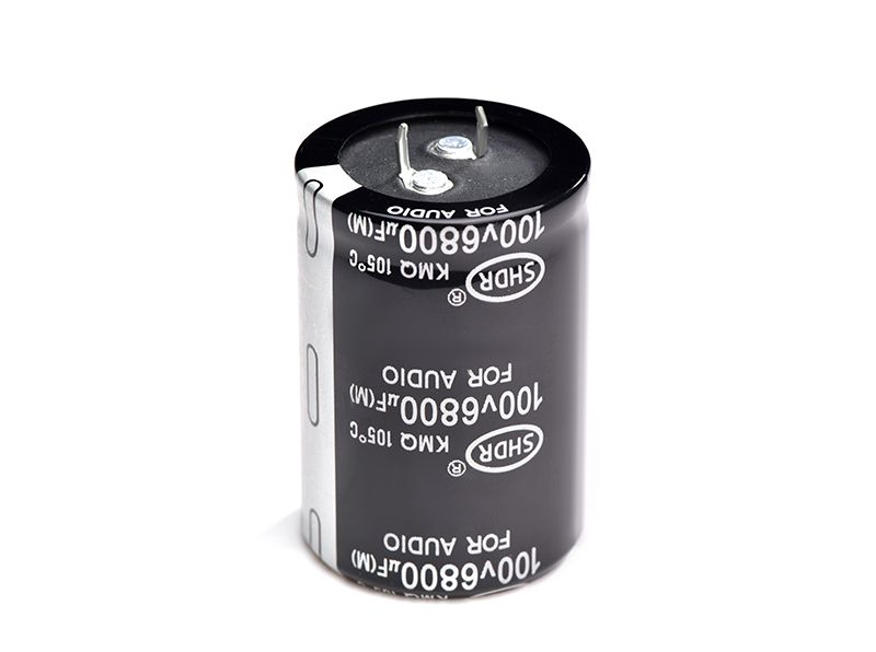
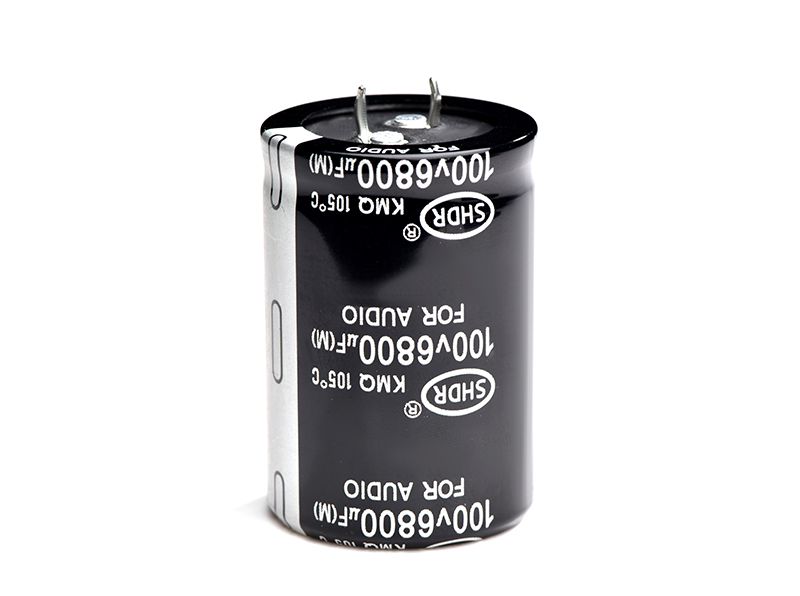
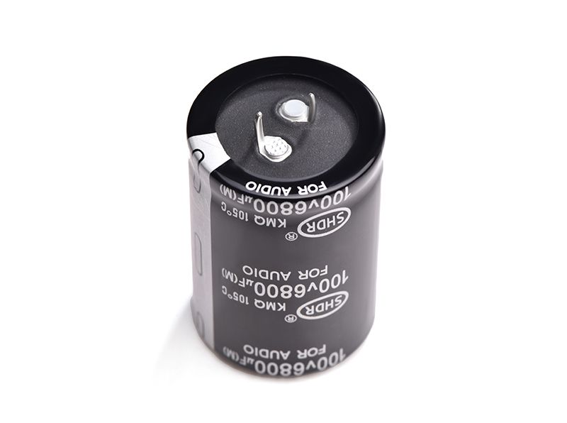
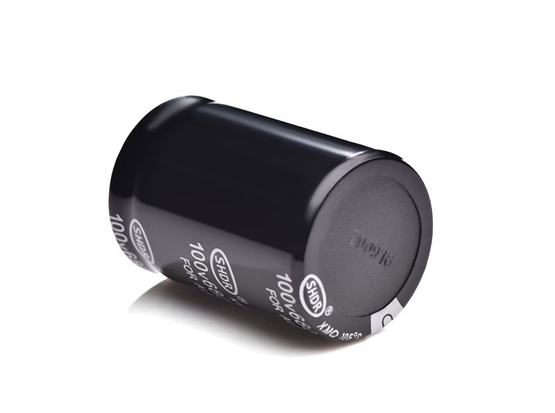
Horn Capacitor 6800uf100v
SHDR® Application Notes
What do the Q and D values of a capacitor mean and why are they important?
When doing RF, pay special attention to their Q values when choosing inductors and capacitors. What is the Q value? What does the Q value mean and why is it important?
Quality factor Q: It is a quality indicator that characterizes the ratio of energy stored in energy storage devices (such as induction coils, capacitors, etc.) and resonant circuits to the energy lost per week. The higher the Q value of a component, the better the selectivity of the circuit or network composed of that component.
or Q = reactive power/active power, or ratio of characteristic impedance to loop resistance.
The higher the Q value, the smaller the loss and the higher the efficiency;
The higher the Q value, the better the frequency stability of the resonator, and therefore the more accurate it can be.
How to Understand Q and ESR Values An important performance metric for evaluating high frequency chip capacitors is the figure of merit, Q, or the equivalent series resistance (ESR) associated with it.
In theory, a "perfect" capacitor should behave as a zero-ohm ESR, purely capacitive, non-impedance element. Regardless of frequency, the current through the capacitor leads the voltage by 90 degrees. In fact, capacitors are not perfect, more or less will have a certain ESR value. The ESR of a particular capacitor varies with frequency and is an equation.
This is because the source of ESR is the properties of the conductive electrode structure and the properties of the insulating medium. To model the analysis, treat the ESR as a single series parasitic element. In the past, all capacitance parameters were measured at the standard frequency of 1MHz, but today is a higher frequency world and 1MHz is not enough. The typical parameter values given by a high-frequency capacitor with excellent performance should be: 200MHz, ESR=0.04Ω; 900MHz, ESR=0.10Ω; 2000MHz, ESR=0.13Ω. The Q-value is a dimensionless number that is numerically equal to the reactance of the capacitor divided by the parasitic resistance (ESR). Q varies greatly with frequency because both reactance and resistance vary with frequency. Changes in frequency or capacity can cause very large changes in reactance, so the Q value will also change a lot.
Define the quality factor of a capacitor, the Q value, which is the ratio of the stored power to the power loss in the capacitor:
Qc=(1/ωC)/ESR
The Q value is an important parameter for high frequency capacitors.
self-resonant frequency
Due to the existence of ESL, a resonant circuit is formed together with C, and its resonant frequency is the self-resonant frequency of the capacitor. Before the self-resonant frequency, the impedance of the capacitor decreases with the increase of the frequency; after the self-resonant frequency, the impedance of the capacitor decreases with the increase of the frequency, showing inductance;
As frequency increases, the nonideal model of capacitance becomes more complex:
(C: Capacitance Rp: Insulation resistance and dielectric loss Rs: Lead/electrode resistance L: Lead/electrode inductance)
A typical equivalent circuit of a capacitive device is shown in Figure 1. In this equivalent circuit, the capacitance C is the most important part, and the series resistance Rs and the inductance L are parasitic parameters caused by the device pin leads or electrodes. The parallel capacitance Rp is the reflected capacitance stored between the two pins.
Due to the existence of these parasitic parameters, the total impedance of the real part rather than the ideal capacitive device consists of two parts, the real part and the imaginary part, expressed as:
If the leakage between the electrodes can be ignored, i.e. the impedance of Rp is infinite (or much larger than the impedance of Ls(ESL) Rs(ESR) C with respect to the capacitance C), then the equivalent circuit above can be further simplified to the following ternary model (as shown). where ESL is the equivalent series inductance Ls and ESR is the equivalent series resistance Rs.
From this simplified circuit model, the total impedance of the capacitive device can be obtained as a function of frequency, as shown. Due to the existence of the equivalent series inductance LS, as the signal frequency f increases, the capacitive reactance XC of the capacitor C decreases, while the inductive reactance XL of the equivalent series inductance Ls of opposite polarity increases. At some frequency f0, XC = -XL. At this time, the total impedance of the capacitive device |Z|=Rs, we call this frequency point f0 as the self-resonant frequency (SRF). When it is less than the SRF frequency, the device has capacitive characteristics. Inductance characteristics
The Q value is equivalent to the reciprocal of the D value. The loss angle is the D value: generally the D value of the electrolysis
Product Picture


Copyright © Guangzhou Shenghe Electronic Technology Co., Ltd. All Rights Reserved Sitemap | Powered by
