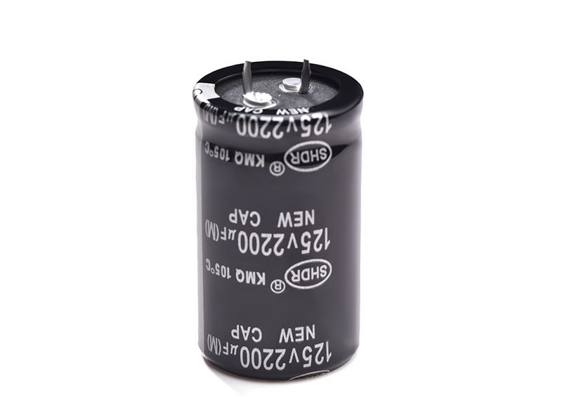
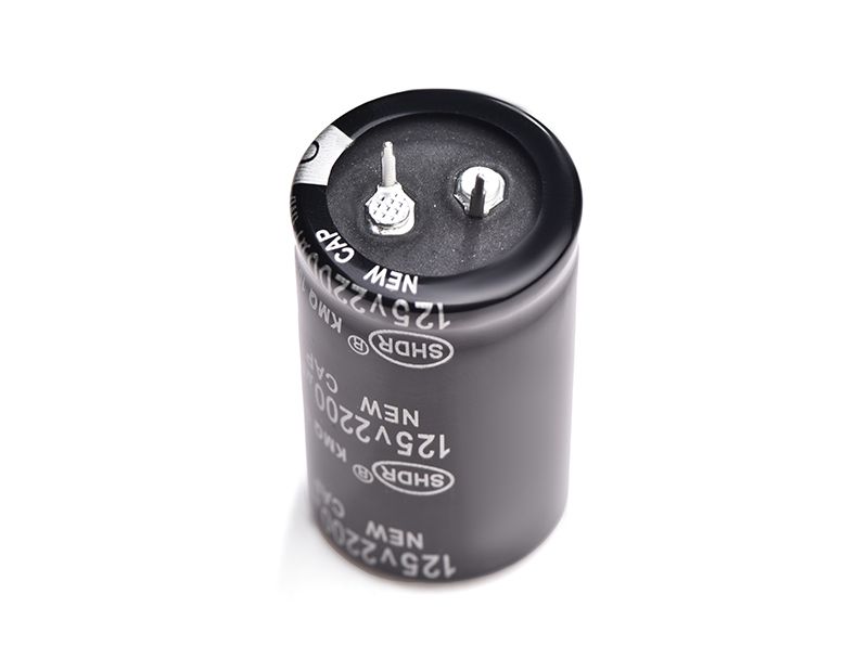
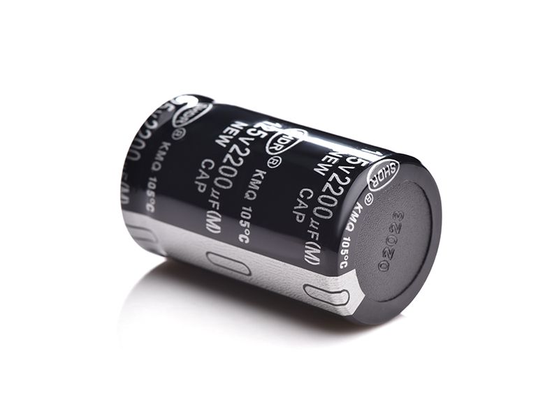
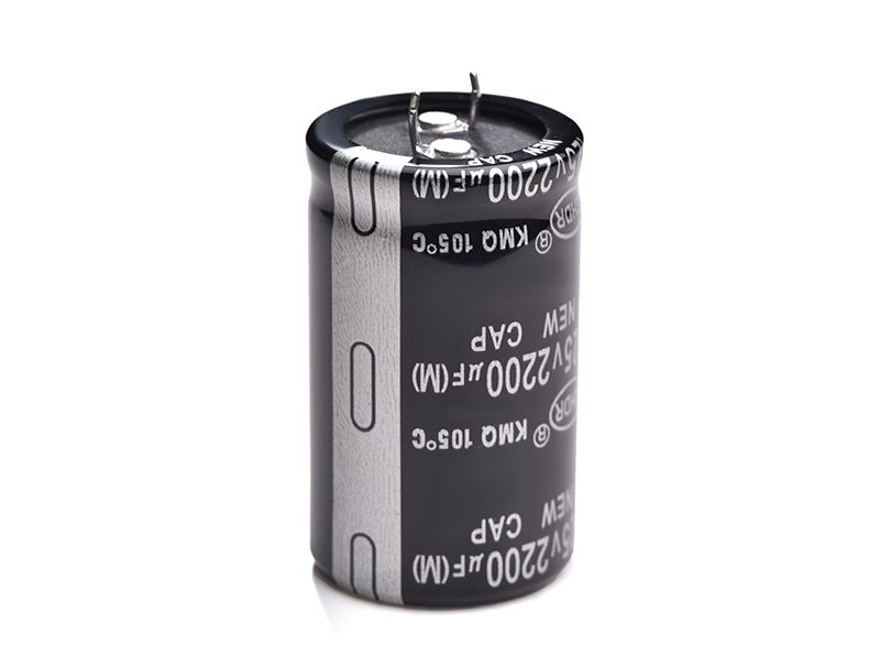
Snap in Ac Super Capacitor
SHDR® Application Notes
Electrolytic capacitor
Electrolytic capacitors are a type of capacitors, the metal foil is the positive electrode (aluminum or tantalum), the oxide film (aluminum oxide or tantalum pentoxide) that is close to the positive electrode is the dielectric, and the cathode is made of conductive materials and electrolytes (the electrolyte can be liquid or tantalum pentoxide). Solid) and other materials together, because the electrolyte is the main part of the cathode, so the electrolytic capacitor is named. At the same time, the positive and negative electrolytic capacitors should not be wrongly connected. Aluminum electrolytic capacitors can be divided into four categories: lead-type aluminum electrolytic capacitors; horn-type aluminum electrolytic capacitors; bolt-type aluminum electrolytic capacitors; solid aluminum electrolytic capacitors.
Basic Information
Chinese name Electrolytic capacitor
Foreign name electrolytic capacitor
Category Capacitor
Features Large capacity
Features
Features of electrolytic capacitors: The capacitance per unit volume is very large, tens to hundreds of times larger than other types of capacitors.
Feature 2 of electrolytic capacitors: The rated capacity can be very large, and can easily achieve tens of thousands of μf or even a few f (but cannot be compared with the electric double layer capacitance).
Three characteristics of electrolytic capacitors: the price has an overwhelming advantage over other types, because the components of electrolytic capacitors are all common industrial materials, such as aluminum and so on. The equipment for manufacturing electrolytic capacitors are also common industrial equipment, which can be mass-produced with relatively low cost.
principle
Electrolytic capacitors usually use metal foil (aluminum/tantalum) as the positive electrode, and the insulating oxide layer of the metal foil (alumina/tantalum pentoxide) as the dielectric. Electrolytic capacitors are divided into aluminum electrolytic capacitors and tantalum electrolytic capacitors based on their positive electrodes. capacitor. The negative electrode of aluminum electrolytic capacitors is composed of thin paper/film or electrolyte polymer soaked in an electrolyte (liquid electrolyte); the negative electrode of tantalum electrolytic capacitors is usually made of manganese dioxide. Electrolytic capacitors get their name because they all use electrolytes as negative electrodes (note the distinction from dielectrics).
application
Polar electrolytic capacitors usually play the role of power supply filtering, decoupling, signal coupling, time constant setting, and DC blocking in power supply circuits or intermediate frequency and low frequency circuits. Generally, it cannot be used in AC power supply circuits. When used as filter capacitors in DC power supply circuits, the anode (positive pole) should be connected to the positive terminal of the power supply voltage, and the cathode (negative pole) should be connected to the negative terminal of the power supply voltage. , otherwise the capacitor will be damaged.
Non-polar electrolytic capacitors are usually used in speaker divider circuits, TV S correction circuits and single-phase motor starting circuits.
Electrolytic capacitors are widely used in household appliances and various electronic products, with a large capacity range, generally 1~33000μF, and a rated working voltage range of 6.3~700V. The disadvantage is that the medium loss, the capacity error is large (the maximum allowable deviation is +100%, -20%), the high temperature resistance is poor, and the storage time is long and it is easy to fail.
The polarity of the electrolytic capacitor, pay attention to observe that on the side of the electrolytic capacitor, "-" is the negative electrode and "+" is the positive electrode. If the positive and negative electrodes are not marked on the electrolytic capacitor, it can also be judged according to the length of its pins. It is the positive pole, and the short leg is the negative pole.
develop
In terms of current output, aluminum electrolytic capacitors occupy the second place in capacitors. This type of capacitor was originally a general DC capacitor, but now it has developed from DC to AC, from low temperature to high temperature, from low voltage to high voltage, from general type to special type, from general structure to chip, flat, book formula and other structures. Its upper limit capacity has been extended to about 4F, the frequency of use has reached 30kHz, the operating temperature range has reached -55℃-125℃, some even as high as 150℃, and the rated voltage has reached 700V. In short, the development of aluminum electrolytic capacitors is getting wider and wider. The foundations leading to these developments are as follows:
1. On the material
The aluminum foil used now is very elegant in composition and structure. High purity is no longer required, eg, for anode foils, to be of adequate purity. In order to improve the number of initial corrosion points, mechanical strength and performance of dielectric oxide film, some impurities should be appropriately contained in the foil. And some alloy foils are used. In terms of structure, for low-voltage foils, the cubic structure is not required to account for a large proportion, but for high-voltage foils, this structure is required to account for more than 80% to 90%. For cathode foil, in order to improve its specific volume, alloy aluminum foil with a certain impurity content with random orientation of crystal grains is required. The working electrolyte consists of three components, namely solvent, solute and additives. For example, the electrolyte that has been used for a long time is composed of ethylene glycol, glycerol, boric acid and ammonia water. Due to the development of aluminum electrolytic capacitors, this electrolyte is far from meeting the requirements, so many new electrolytes have been produced to reduce the operating temperature range of the capacitor (such as -55℃--l25℃). The formula principles of these new electrolytes are: ① Mixing with two solvents to achieve complementarity. ② Use two weak acids to provide the required two anion groups. ③Add alkali, such as organic amine, to adjust the pH value and flash voltage of the electrolyte. Change its resistivity. ④ Additives to improve the characteristics of electrolyte, such as phosphoric acid or its salts to prevent hydration of aluminum oxide film, dinitrobenzene to absorb hydrogen, etc., and ethylene oxide to improve the flash voltage of electrolyte.
2. In terms of craftsmanship
In addition to the mechanization and automation of production, the progress in the process of aluminum electrolytic capacitors is mainly two processes of corrosion phase energization. The corrosion coefficient of aluminum foil is not only very high (low-voltage capacitor foil has reached 100, and high-voltage capacitors have reached 25), but also aluminum foil with different pit shapes can be etched according to the performance requirements of capacitors. The etching process is a dynamic balance process of the type of etching solution, concentration, temperature, original foil composition, structure, surface state, foil speed during etching, and power supply type, waveform, frequency, voltage, etc. The question is how to get the best dynamic balance and how to determine the best balance according to the requirements. Therefore, it cannot be said that the current etching process has reached the optimum state.
The current energizing process can produce high-quality dielectric oxide films, and can also produce different dielectric oxide films according to different requirements. Capacitors are amorphous films. The biggest progress of the energization process is to convert the aluminum hydroxide film into a dielectric aluminum oxide film and to form a waterproof layer on its surface. In addition, it can eliminate the defects and cracks of the dielectric film.
3. Structurally
The structure of aluminum electrolytic capacitors has been diversified, in addition to the above-mentioned liquid aluminum electrolytic capacitors. There are also solid aluminum electrolytic capacitors. There are two main structural forms, one is foil-wound, the other is aluminum powder sintered porous block, and the solid electrolyte used is mainly MnO2. The structure of aluminum electrolytic capacitors has been diversified, such as double anode structure, opposite cathode structure, book structure, triangular structure, and chip structure. Among them, the emergence of chip aluminum electrolytic capacitors is another progress of aluminum electrolytic capacitors. Because if there is no aluminum foil with high specific volume, high temperature-resistant electrolyte, excellent sealing structure and fine processing technology, it is difficult to make a chip aluminum electrolytic capacitor that meets the requirements. At present, the chip rate is still relatively low. low level.
future
The YDK-700V capacitors developed by capsun and TDK are made of 820V, which has been used in the audio of the Japanese capsun group, which is of great epoch-making significance. In the future, the performance of aluminum electrolytic capacitors will be further developed with the advancement of technology. The regular capacitor volume of 700V100uf is usually 35*80-100MM or 50*80-96MM and the price is about 22 US dollars. Currently used in the world's top capsun, YAMAHA audio is widely exported to European and American high-end hotels, the price of 1200 US dollars to millions of dollars a set of audio is expensive, mostly used in aristocratic families and hotels. Small-volume and high-capacity supercapacitors are also being gradually developed.
The test method and test conditions for leakage current of aluminum electrolytic capacitors are as follows: at 25°C, the capacitor under test is connected in series with a 1000Ω protective resistor connected to the rated voltage, and the leakage current is measured. After applying the voltage for 5 minutes, the leakage current does not exceed the maximum value in the specification. Small-capacity aluminum electrolytic capacitors can use 1min test results, and large-capacity aluminum electrolytic capacitors will require longer test time. It can be seen from the characteristic curve that the current will infinitely approach the final "leakage current" value - supplementary oxidation The current value required by the aluminum medium. The dissipation factor (DF) of the electrolytic capacitor can be understood as the reactive power of the electrolytic capacitor and the active power of the equivalent series resistance (ESR) under the excitation of alternating current. Obviously, this is the ratio of capacitive reactance to equivalent series resistance (ESR). An RC circuit in an AC circuit, and the ratio is very much like the opposite side of the trigonometric function - the tangent function. Therefore, the dissipation factor (DF) of electrolytic capacitors is also called loss tangent in many technical documents. The voltage indicators of aluminum electrolytic capacitors mainly include rated DC voltage, rated surge voltage, instantaneous overvoltage and reverse voltage.
Rated DC voltage VR The rated DC voltage VR is the continuous working voltage allowed by the capacitor within the rated temperature range, which includes the sum of the DC voltage and the pulsating voltage or the continuous pulse voltage between the two electrodes of the capacitor. Usually, the rated voltage of tantalum capacitors is marked on the surface of the capacitor. Usually rated voltage ≤ 100V T491B107M004AT is a "low voltage" tantalum capacitor, while rated voltage ≥ 150V is a "high voltage" capacitor
Product Picture


Copyright © Guangzhou Shenghe Electronic Technology Co., Ltd. All Rights Reserved Sitemap | Powered by
