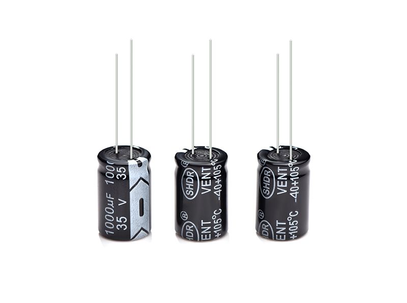
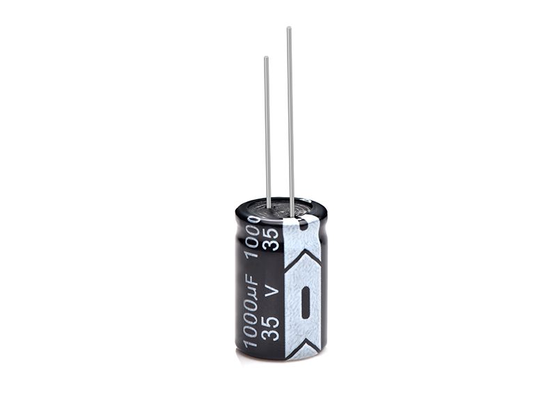
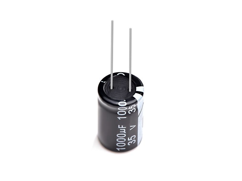
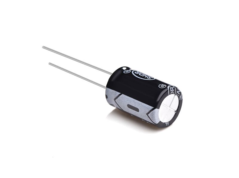
Capacitor 1000uf 35v
A capacitor with a capacitance value of 1000 microfarads (uF) and a voltage rating of 35 volts (V) is commonly available in the market. This specification indicates that the capacitor can store a charge of 1000 microfarads when a voltage of up to 35 volts is applied across its terminals.
SHDR® Application Notes
1. Polarity
SHDRCAP is a solid aluminum electrolytic capacitor, positive and negative electrode. Do not reverse polarity when using. if it matches Reverse polarity may shorten its life due to increased leakage current or short circuit.
2. Inhibit circuit
Due to possible increased leakage current during welding and other process, SHDRCAP cannot be used in the following circuits.
1) High impedance circuit;
2) Coupling circuit;
3) Time-limited constant circuit;
4) Two or more capacitors connected in series for higher tolerance Voltage;
5) Circuits affected by large leakage currents.
* In addition to leakage current fluctuations, operating conditions, High and low temperature, damp heat and other characteristics. The endurance stated in the specification affects the capacitance. This Fluctuations in capacitance can cause problems if used as a time-limited constant capacitor, which is extremely sensitive to fluctuations in capacitance capacitance. So don't use it as a time-limited constant capacitor. Alternatively, please contact Hunan Aihua Group Co., Ltd. using two or More SHDRCAPs in series for withstand voltage.
3. Overvoltage
Overvoltage must not be applied even momentarily as it may cause a short circuit.
4. Sudden charge and discharge
Sudden charging and discharging are prohibited (for maintaining high reliability). When charging suddenly or it is recommended to use a protection circuit discharge can cause excessive inrush current because this causes short circuits and large leakage currents. Use a protective circuit in an emergency current exceeds 10A. If the inrush current exceeds 10 times the maximum value The allowable ripple current of AishiCAP, be sure to insert a protection resistor. When measuring leakage current, charge and discharge are about 1kΩ.
5. Precautions when welding
Welding conditions should be within the specified range Specification. If the specification is not followed, it is possible The leakage current increases sharply and the capacitance decreases. Matters needing attention before installation:
a) Do not reuse capacitors that have been assembled into a set and energized.
b) Capacitors removed to measure electrical characteristics.
It also cannot be reused during periodic inspections. After the capacitor has been stored for one year, the leakage current may increase. In this case, apply the rated voltage for 2 hours at 105°C and a 1 kΩ resistive load.
c) Reflow soldering
Do not reflow solder radial lead capacitors.
d) Treatment after welding
Do not tilt, bend or twist the SHDRCAP;
Do not move the PCB with the SHDRCAP itself.
When stacking PCBs, make sure that AishiCAP does not touch other PCB or assembly.
Do not dump SHDRCAP with other objects.
6. Application of SHDRCAP in industrial equipment
To ensure reliability, when using AishiCAP in industrial equipment, Proper design is required.
7. Application of SHDRCAP in human life equipment
For use in equipment involving human life (such as space equipment, aeronautical equipment and atomic equipment, etc.), yes
Be sure to consult Guangzhou Shenghe Electronic Technology Co., Ltd. Do not use the product. There is no approval document from Guangzhou Shenghe Electronic Technology Co., Ltd.
8. Storage
1) Store the SHDRCAP at a temperature between 5 and 35°C (if between 35 and 85°C, should be less than three months), and 75% relative humidity away from direct sunlight and stored SHDRCAP is stated in the package if possible.
2) It is recommended that you open the bag and use Get up as early as possible.
3) Store capacitors in places without water, oil or salt water or in a condensing state.
4) Do not store SHDRCAP in any area full of toxic gas (including hydrogen sulfide, sulfurous acid, nitrous acid, chlorine and ammonia).
5) Store capacitors in a place free from ozone, UV light or radiation. Before opening: within 1 year after delivery After opening: within 7 days
9. Cleaning
Regarding HCFC, soaking with high concentration alcohol, Petroleum and terpenes, water or surfactants, etc. Solvents (single or mixed), in manufacturer's cleaning Recommended by ultrasonic, boiling, and evaporation. If you need more details, please contact us.
10. SHDRCAP circuit design considerations
10.1 Performance
Use SHDRCAP within the rated performance range defined here Specification.
10.2 Operating Temperature and Ripple Current
If SHDRCAP is used at temperatures above the upper limit Category temperature (105°C), or excess ripple current flows through SHDRCAP, very likely to reduce service life or The increased leakage current causes the SHDRCAP to be defective.
10.3 Leakage current
Leakage current of SHDRCAP may increase slightly due to soldering condition. The application of DC voltage enables the capacitor to Self-healing, resulting in less leakage current Gradually.
10.4 Applied Voltage
For SHDRCAP reliability, it is recommended that the voltage
The voltage applied to SHDRCAP should be less than 80% of the rated voltage.
The peak value of DC and AC voltage should not exceed their rated value Voltage.
10.5 Failure Modes
SHDRCAP contains conductive polymers. The end of life is mainly because Random failure modes, mostly short circuits. In the case of a short circuit, SHDRCAP can overheat with continuous current, then Al The case of SHDRCAP will separate due to increased internal pressure.
Use of 1000uF 35V capacitor
A 1000uF 35V capacitor can be used for various purposes in electronic circuits. Here are a few common applications:
Power Supply Filtering: Capacitors are often used in power supply circuits to filter out noise and stabilize voltage levels. A 1000uF capacitor can store a relatively large amount of charge, making it effective for smoothing out voltage fluctuations and reducing ripple in power supply circuits.
Energy Storage: Capacitors can store electrical energy and release it quickly when needed. A 1000uF capacitor with a higher voltage rating can store a significant amount of energy, making it useful for applications that require short bursts of power, such as in audio amplifiers or motor control circuits.
Timing and Coupling: Capacitors can be used in conjunction with resistors to create timing circuits, such as oscillators or time-delay circuits. They can also be used for coupling signals between different stages of an electronic circuit while blocking DC (direct current) components.
Audio Applications: In audio circuits, capacitors are commonly used for coupling, decoupling, and filtering purposes. A 1000uF capacitor can be employed to block DC and allow only the AC audio signal to pass through.
Motor Starters: Capacitors with higher capacitance values, such as 1000uF, are sometimes used in motor starter circuits to provide an initial boost of power to start the motor.
Product Picture


Copyright © Guangzhou Shenghe Electronic Technology Co., Ltd. All Rights Reserved Sitemap | Powered by
